Power LED is off
Check the power pins are seated. If the pack total voltage is below this model’s minimum, an external DC supply or booster module is required — the board will not start from the pack alone.

Support
Fault codes, wiring rules and the questions our after-sales team answers most often. If the table below does not resolve your fault, email zhou@jkess.com with a short video of the LEDs and a screenshot of the firmware version from the app.
| Green | Steady — Power applied and normal |
|---|---|
| Blue | Steady — Connected to the app over Bluetooth |
| Blue | Blinking — Connection failed — not paired |
| Yellow | Blinking — Balancing in progress |
| Yellow | Steady — Balancing complete — pack inside your threshold |
| Red | Steady — Detected cell count does not match the count set in the app |
| Red | Blinking — Balance-wire resistance too large — a cell tap is not making contact |
| Blue | Steady — Connected |
|---|---|
| Blue | Blinking — Not connected |
| Green | Blinking — Balancing |
| Green | Steady — Balance complete |
| Red | Steady — Internal fault |
| Red | Blinking — Battery test failed |
| On | Balancing is active |
|---|---|
| Off | Board is in undervoltage sleep, or not receiving a valid start voltage |
The buzzer is switched off by default — enable it in the app’s settings to hear these.
| Event | What you hear | Meaning & action |
|---|---|---|
| Power-up | 3 beeps (4 on the 4A model), green LED steady | Normal start-up |
| Balance start | 1 beep, yellow LED blinking | Normal |
| Balance complete | 1 beep after a 3-minute voltage-recovery wait, yellow LED steady | Normal |
| Parameter accepted | Single “di” | The app setting was written |
| Fault: data storage | 2 beeps per second + red LED | Hardware data-storage fault — contact support |
| Fault: Bluetooth | 3 beeps per 0.5 s + red LED | Bluetooth communication error — contact support |
| Fault: hardware | 4 beeps per 0.5 s, red LED lit only between beeps | Hardware fault or supercapacitor overvoltage — stop and contact support |
Check the power pins are seated. If the pack total voltage is below this model’s minimum, an external DC supply or booster module is required — the board will not start from the pack alone.
Turn Bluetooth on and grant the app location permission. Re-run the Bluetooth scan and restart the app before each attempt. If it still fails, close the app from background and reconnect.
The first cell (B0 tap) must be above 2.4 V — the board takes its start-up supply from it. Charge the pack above that, and it starts on its own.
Correct the cell count in the app. Boards default to 24S on first power-up, so a red LED before you have configured it is expected, not a fault.
Check the cell-to-connector contact on every tap. If the contact is good, replace that lead.
Check the wiring one tap at a time, then fine-tune using the voltage calibration reference in the app.
The acquisition cable has probably come loose at the connector or the tap. Re-seat it, and check the fuse on that string if the pack has one.
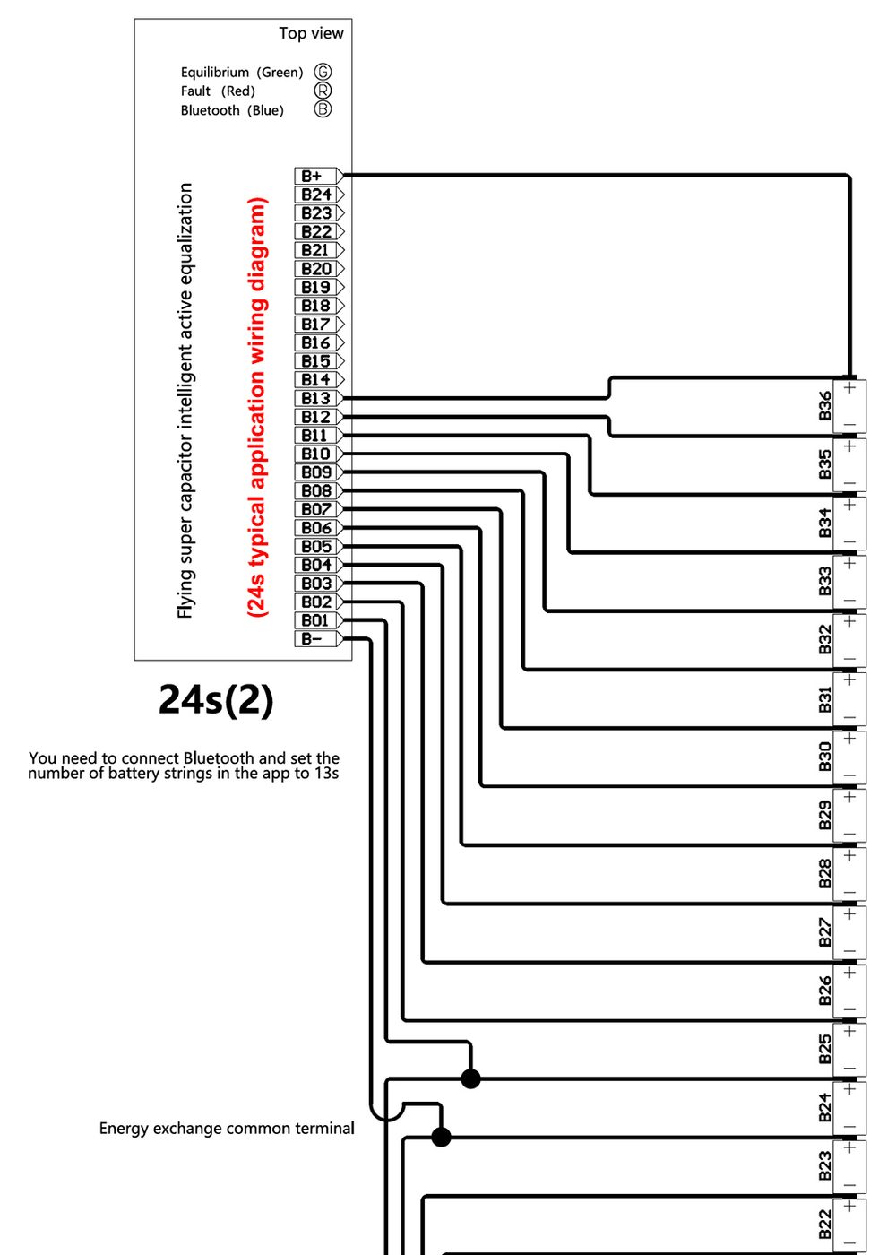
A cascade needs at least one cell shared between the two boards as the energy-exchange common node. Ask us for the wiring diagram for your configuration.
Re-power the board, restart it and record a short video of the LEDs and the app screen, then send it to support. Include a screenshot of the firmware version shown in the app.
Most boards that come back to us as failures were wired in one of these ways. The rules are short, and the reasons are real.
Solder the tailed terminals to the pack before plugging them into the balancer — never push a loose tail into a connector.
On smart balancers, insert the B0 cell cable before the B24 cable. In the wrong order the board can operate abnormally or be damaged.
On the 15EB, IN– always goes to pack negative and IN+ to pack positive. In a cascade, IN– goes to the lowest and IN+ to the highest cell of that unit’s own sub-pack.
Connectors with more than 13 pins must be inserted diagonally, B– side first. Inserted square they can crack the board.
The shared energy-exchange node is the one joint a cascade depends on. Verify it for cold or false solder before powering up.
Do not tie unused tap pins to anything, and insulate the board — capacitor boards have components on both sides.
Operate between −20 °C and +55 °C (+60 °C on capacitor and inductor boards), store at 0 – 35 °C and under 80 % RH, and take normal ESD precautions when handling.
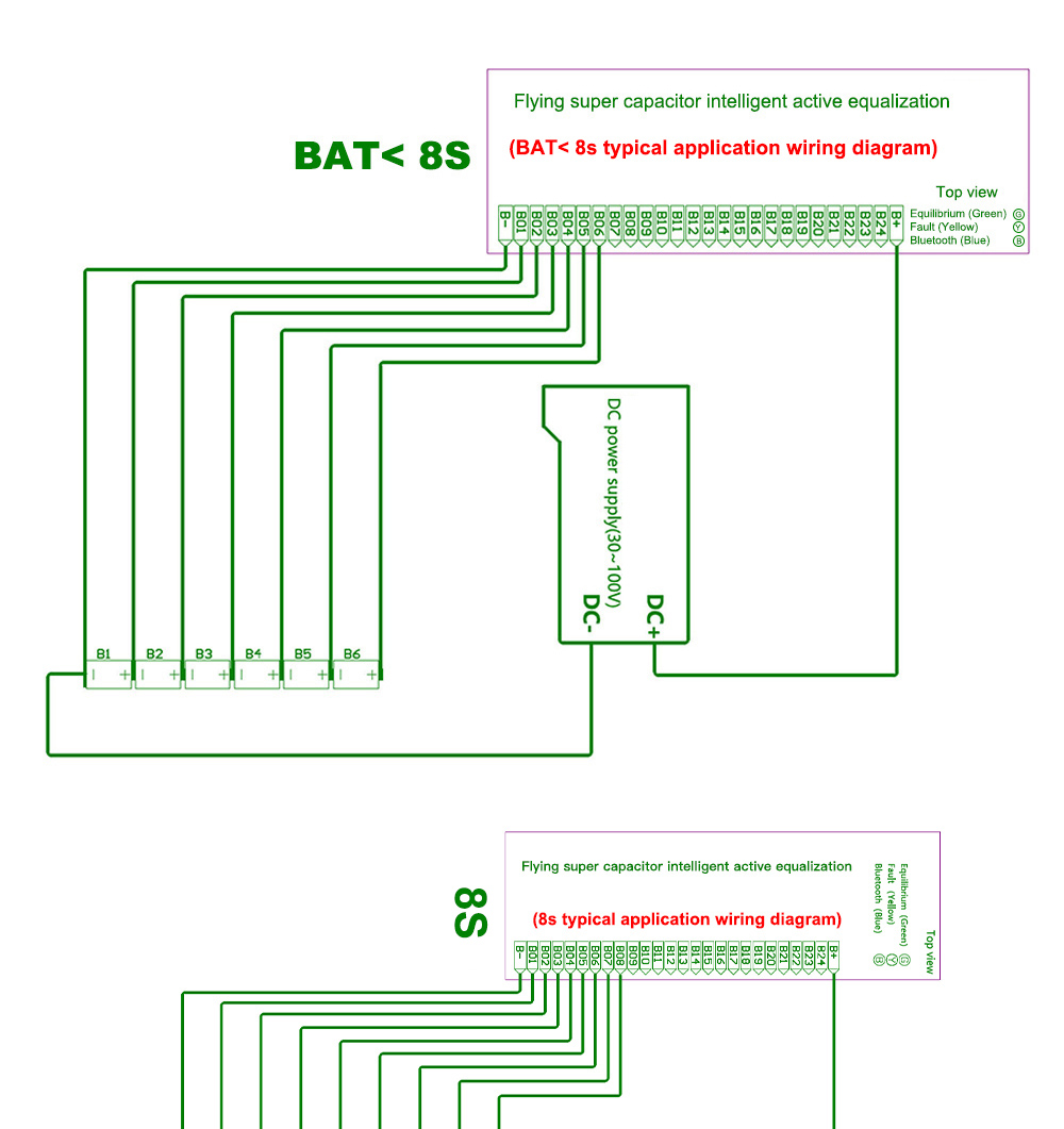
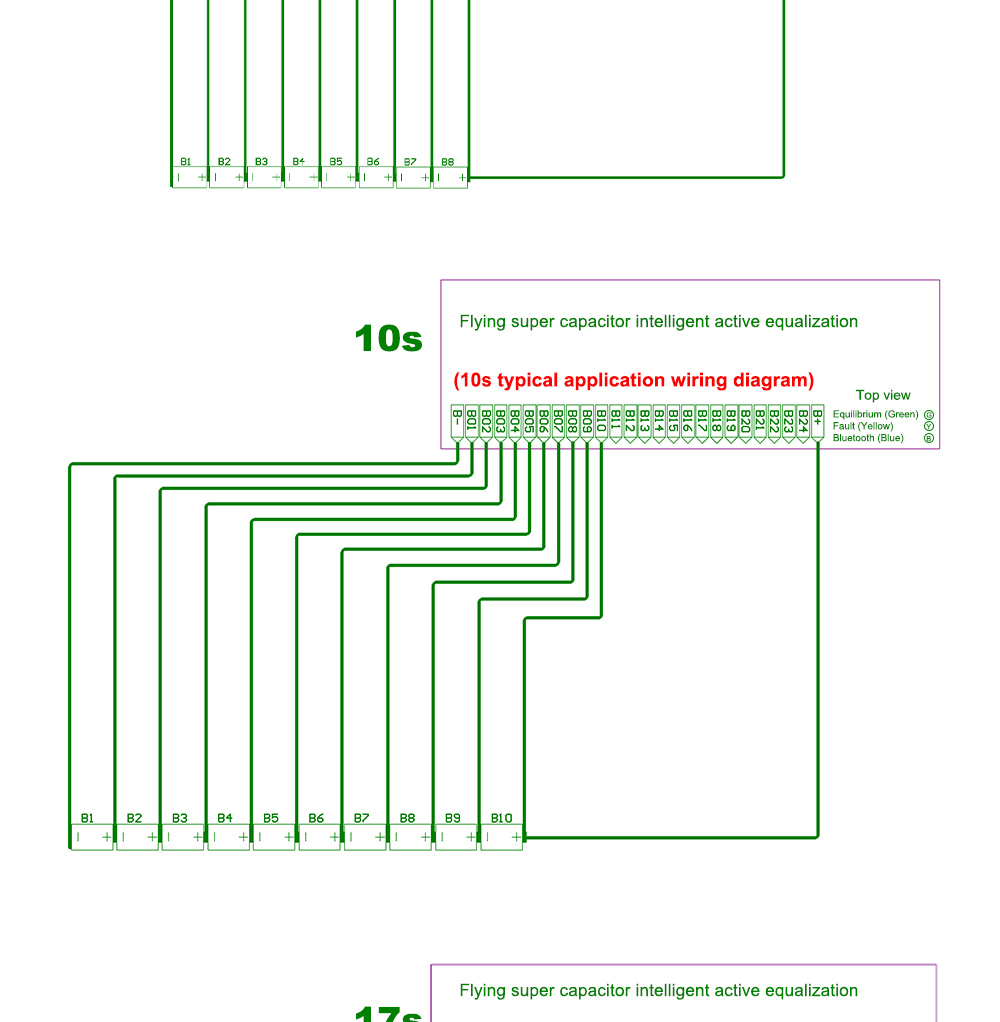
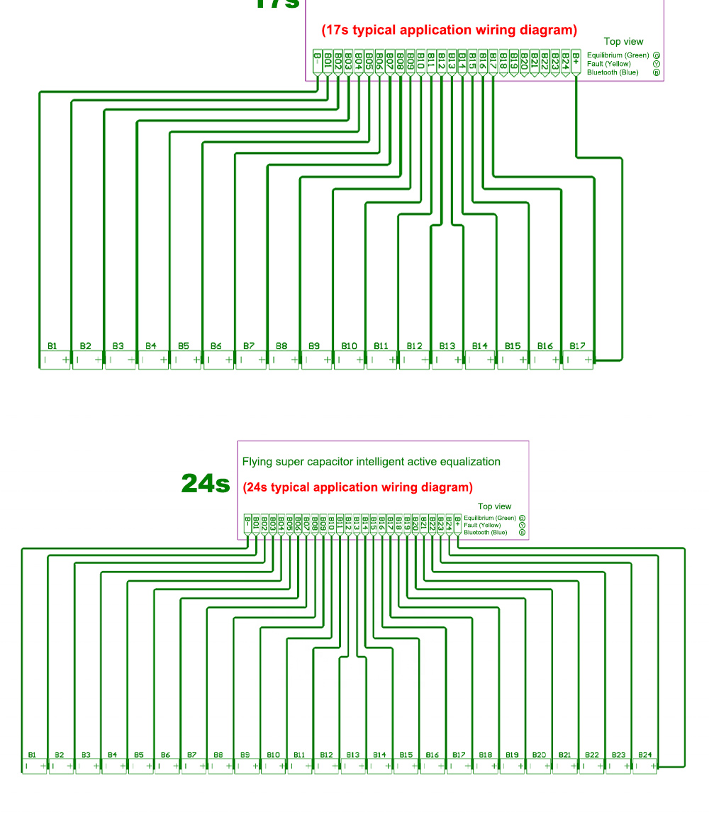
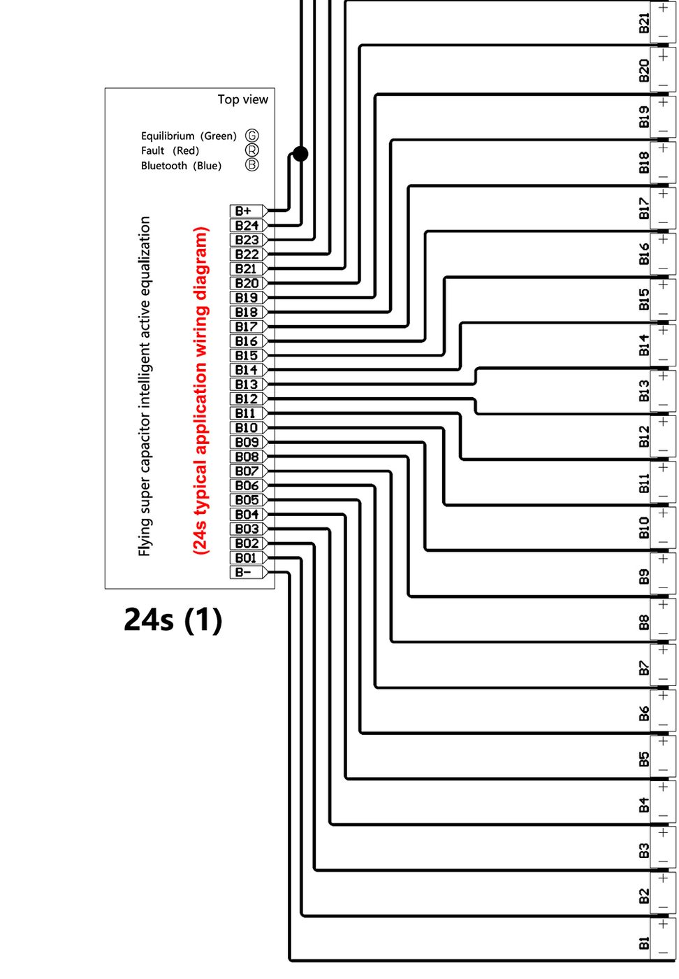
Start at 0.1C of pack capacity or below. The setting is written over Bluetooth and takes effect immediately, confirmed by a single tone.
0.005 V for cells above 50 Ah, 0.01 V for smaller ones. Start and stop conditions must persist for two minutes before the board acts, so surface charge will not make it hunt.
If the strongest and weakest cells keep swapping places after a cycle, the current is too high. The board halves it automatically after a three-minute wait; lowering your setting is the better fix.
On the Smart Active Balancer range, no. The current you set in the app is the current the board delivers, so a 300 Ah pack balances just as hard as a 30 Ah one. On the capacitor boards it is the opposite: current is proportional to the voltage difference between cells — roughly 1 A at 0.08 V of difference, rising to a 5.5 A peak.
Keep maximum balance current at or below 0.1C of your pack capacity — a 20 Ah pack should run at 2 A or less. Higher settings do not balance a large pack faster in any useful sense; they just push more current through the same wiring.
A sensible target depends on cell size. For cells above 50 Ah, 0.005 V; below 50 Ah, 0.01 V. Start and stop detection needs the condition to hold for two minutes before acting, so transient surface charge does not make the board hunt.
That is over-balancing. Lower the current you have set. The board also guards itself: it waits three minutes for voltages to settle, and if the maximum and minimum cells have swapped it halves its own current — 15 A to 7.5 A, 10 A to 5 A, 4 A to 2 A — and repeats until the spread is inside your window.
Not usually — every line can run from the pack itself. You need an external supply when the pack total is too low to start the board: below 12 V on the 15A model, below 25 V on the 4A model, and for 2S or 3S connections on the 8A and 10A. The 8A, 10A and 15A accept 12 V – 100 V DC (120 V on the 15A); the 4A accepts 20 V – 100 V.
NCM (ternary), LiFePO4 and LTO on all smart balancers, with cell-count minimums that differ by chemistry — see any product page. On capacitor boards NCM and LiFePO4 are the factory default; LTO is enabled by soldering the jumper across pads 1 and 2.
Short the two password-reset pins for ten seconds on the 4A board. On the 8A, hold the reset button for ten seconds; if nothing happens, check that the supply is adequate. If neither works, contact support.
Yes. Cascade two or more boards so that each pair shares at least one cell as the energy-exchange common node. The 10A manual documents a five-unit cascade covering 79S, where each module is set to 17S in the app and the last to 15S.
No. The boards have no user-serviceable parts inside, and changing the factory working-voltage setting voids the safety certification.
Nothing on top of the listed price — every price on this site is delivered, worldwide. We choose the route and carrier against your address and the weight of the order: express courier (DHL, FedEx or UPS) in 3 – 7 working days for samples and small orders, air freight in 7 – 12 working days with door-to-door available, or sea freight in 25 – 40 days for pallet quantities. Import duty and local VAT are not part of our invoice and are collected by your customs authority on arrival.
One year from shipment — or, if installation is delayed more than a month through no fault of ours, one year from the 31st day after shipment. We repair or replace at our discretion. Warranty is void for misuse, non-supplied parts, unauthorised disassembly or modification, operation outside specification, damage in transit or storage we did not arrange, and force majeure.
One year from shipment, or one year from the 31st day after shipment if installation is delayed more than a month. We repair or replace at our discretion. Every board ships conformal coated and run-in against a real pack.
Opening a claim. Email zhou@jkess.com with your order number, the model, a short video of the LEDs and buzzer behaviour, and a screenshot of the firmware version shown in the app. Please do not disassemble a board before contacting us — it usually costs the warranty rather than explaining the fault.